


Mark V Circuit-Switcher
Effective overvoltage control for capacitor-bank switching and transmission line full-load-current switching applications
The S&C Mark V Circuit-Switcher is the perfect solution for growing your grid without spending time and money on a new substation.
The tower-mounted device installs into existing rightaways without the need to secure a permit or buy land, allowing you to efficiently sectionalize transmission lines, transfer loads, and connect new customers. These power-operated Circuit-Switchers can be SCADA-operated even in the most remote locations.
Mark V Circuit-Switchers are available in a variety of mounting styles with optional pre-insertion inductors for use in single-bank and multiple-bank (back-to-back) capacitor switching. When fitted with these pre-insertion inductors, the device can minimize capacitor-bank switching transients, markedly improving power quality and reliability.
Mark V Circuit-Switchers are available with continuous current ratings of 1200, 1600, and 2000 amperes.
The Mark V Circuit-Switcher uses an in-series circuit-breaking interrupter and a circuit-making and isolating disconnect, making it especially suited for the switching and protection of transformers, lines, cables, capacitor banks, and line-connected or tertiary-connected shunt reactors. The Mark V Circuit-Switcher is available in three styles—Vertical-Break, Center-Break, and Integer.
Performance-proven through over 40 years of reliable service
- Unsurpassed capacitor switching — pre-insertion inductors dramatically reduce inrush currents, tame damaging overvoltages that can shut down sensitive adjustable-speed drives
- Unlimited installation flexibility — can be custom-tailored to fit any structure, phase spacing or bus height
- Low maintenance interrupters — hermetically sealed to eliminate the hassle and expense of field filling with SF6 . . . ensure long, trouble-free life
- Superb mechanical and electrical operating life . . . proven in the lab and in the field, backed by a full 5-year warranty
For more information regarding transient control, refer to the technical paper titled “Selecting a Capacitor-Switching Overvoltage Control Method Effective in Preventing Nuisance Tripping of Adjustable-Speed Drives”.
Mark V Circuit-Switchers are also well-suited for transformer, line, cable, and reactor switching and protection. For more information, see S&C Specification Bulletin 711-31.
Voltage and Continuous, Short-Time, and Fault-Closing Ratings
| kV | Amperes, RMS | |||||
|---|---|---|---|---|---|---|
| Nom. | Max | BIL | Cont. | Short-Time | Fault-Closing, Duty-Cycle, One-Time | |
| Mom. | 3-Second | |||||
| 34.5 | 38 | 200 | 1200 | 61 000 | 40 000 | 30 000 |
| 46 | 48.3 | 250 | 1200 | 61 000 | 40 000 | 30 000 |
| 69 | 72.5 | 350 | 1200 | 61 000 | 40 000 | 30 000 |
| 115 | 121 | 550 | 1200 | 61 000 | 40 000 | 30 000 |
| 138 | 145 | 650 | 1200 | 61 000 | 40 000 | 30 000 |
| 1600♥ | 70 000 | 43 750 | 40 000 | |||
| 2000♥ | 80 000 | 50 000 | 40 000 | |||
| 161 | 169 | 750 | 1200 | 61 000 | 40 000 | 30 000 |
| 230 | 242 | 900 | 1600 | 70 000 | 43 750 | 40 000 |
| 2000 | 80 000 | 50 000 | 40 000 | |||
| 345 | 362 | 1300 | 1600 | 70 000 | 43 750 | 40 000 |
| 2000 | 80 000 | 50 000 | 40 000 | |||
♥ 1600 and 2000 amperes continuous available in Three-Pole Center-Break style only.
Interrupting Current Ratings for Transformer Switching and Protection
| Class | Qualifications | Maximum Amperes, Interrupting RMS Symmetrical |
|---|---|---|
| Parallel Switching | Max 60-hertz recovery voltage: 90 kV RMS and 150 kV RMS | 1200/1600/2000♥ |
| Load Dropping and Magnetizing Current Switching | Transformers connected to solidly grounded-wye on the primary (Circuit-Switcher) side and delta on the secondary side | 1200/1600/2000♥♣ |
| All other connections of transformers | 1200/1600/2000♥♣ | |
| Fault Interrupting | Primary faults with the total connected length of all lines on the source side of the Circuit-Switcher not less than ♠. | 7000 or 8000 |
| Primary faults with the total connected length of all lines on the source side of the Circuit-Switcher less than ♠. | 4000 (3000A for 115-kV single-gap Circuit-Switchers) | |
| Secondary faults — all other connections of transformers | 4000 (3000A for 115-kV single-gap Circuit-Switchers) | |
| Internal faults — see both primary and secondary faults, above | ||
♥ Depending on continuous rating of Circuit-Switcher.
♣ Will switch magnetizing currents associated with such loads.
♠ Total connected length of all ovehead lines (in all directions) including any number of feeders connected to source-side substations as indicated in the table below:
| System Voltage, kV | 34.5 thru 69 | 115 and 138 | 161 | 230 | 345 |
|---|---|---|---|---|---|
| Total Length, Miles | 7 | 15 | 20 | 25 | 40 |
Interrupting Current Ratings for Line Switching and Protection
| Class | Qualifications | Maximum Amperes, Interrupting RMS Symmetrical |
|---|---|---|
| Load Splitting (Parallel or Loop Switching) | Max 60-hertz recovery voltage: 90 kV RMS and 150 kV RMS | 1200/1600/2000♥ |
| Load Dropping | Circuits with all load-side transformers connected solidly grounded-wye on the primary (Circuit-Switcher) side and delta on the secondary side | 1200/1600/2000♥ |
| Circuits with all load-side transformers connected other than as described above. | 1200/1600/2000♥ | |
| Line Dropping | Maximum length of line: 300 miles. | |
| Fault Interrupting | Line or bus faults with the total connected length of all lines on the source side of the Circuit-Switcher not less than ♠. | 7000 or 8000 |
| Line or bus faults with the total connected length of all lines on the source side of the Circuit-Switcher less than ♠. | 4000 (3000A for 115-kV single-gap Circuit-Switchers) | |
♥ Depending on continuous rating of Circuit-Switcher.
♠ Total connected length of all ovehead lines (in all directions) including any number of feeders connected to source-side substations as indicated in the table below:
| System Voltage, kV | 34.5 thru 69 | 115 and 138 | 161 | 230 | 345 |
|---|---|---|---|---|---|
| Total Length, Miles | 7 | 15 | 20 | 25 | 40 |
Interrupting Current Ratings for Cable Switching and Protection
| Class | Qualifications | Maximum Amperes, Interrupting RMS Symmetrical |
|---|---|---|
| Load Splitting (Parallel or Loop Switching) | Max 60-hertz recovery voltage: 90 kV RMS and 150 kV RMS | 1200/1600/2000♥ |
| Load Dropping | Circuits with all load-side transformers connected solidly grounded-wye on the primary (Circuit-Switcher) side and delta on the secondary side | 1200/1600/2000♥ |
| Circuits with all load-side transformers connected other than as described above. | 1200/1600/2000♥ | |
| Cable Dropping (Charging Current) | Shielded and Unshielded Cable | 550 |
| Fault Interrupting | Cable or bus faults with the total connected length of all lines on the source side of the Circuit-Switcher not less than ♠. | 7000 or 8000 |
| Cable or bus faults with the total connected length of all lines on the source side of the Circuit-Switcher less than ♠. | 4000 (3000A for 115-kV single-gap Circuit-Switchers) |
♥ Depending on continuous rating of Circuit-Switcher.
♠ Total connected length of all ovehead lines (in all directions) including any number of feeders connected to source-side substations as indicated in the table below:
| System Voltage, kV | 34.5 thru 69 | 115 and 138 | 161 | 230 | 345 |
|---|---|---|---|---|---|
| Total Length, Miles | 7 | 15 | 20 | 25 | 40 |
Interrupting Current Ratings for Shunt Capacitor Bank Switching and Protection
| Class | Qualifications | Maximum Amperes, Interrupting RMS Symmetrical | |
|---|---|---|---|
| Bank Current Switching | Grounded capacitor bank | Applications on solidly grounded systems through 69 kV | 1000 |
| All other applications | 550 | ||
| Ungrounded capacitor bank | 550 | ||
| Fault Interrupting | Primary faults with the total connected length of all lines on the source side of the Circuit-Switcher not less than ♠. | 7000 or 8000 | |
| Primary faults with the total connected length of all lines on the source side of the Circuit-Switcher less than ♠. | 4000 (3000A for 115-kV single-gap Circuit-Switchers) | ||
♠ Total connected length of all ovehead lines (in all directions) including any number of feeders connected to source-side substations as indicated in the table below:
| System Voltage, kV | 34.5 thru 69 | 115 and 138 | 161 | 230 | 345 |
|---|---|---|---|---|---|
| Total Length, Miles | 7 | 15 | 20 | 25 | 40 |
Interrupting Current Ratings for Reactor Switching and Protection
| Class | Qualifications | Maximum Amperes, Interrupting RMS Symmetrical | |
|---|---|---|---|
| Series Reactor Switching | Refer to the nearest S&C Sales Office. | ||
| Shunt Reactor Switching and Protection (Line-Connected or Tertiary Connected Reactors) | Reactor Current Switching | Reactor wye-connected with solidly grounded neutral | 1000 |
| Reactor delta-connected, or wye-connected with ungrounded neutral | 1000 | ||
| Fault Interrupting | Oil-insulated reactors | 2800 | |
| Air-insulated reactors | 2000 | ||
Pre-insertion inductors are especially suited for limiting transient overvoltages which, through voltage magnification, can result in nuisance tripping of adjustable-speed drives and other sensitive electronic devices. Voltage magnification can occur where power-factor correction capacitors and/or voltage control capacitors are applied on the utility distribution system or on a utility customer’s low voltage bus, and is caused by a near-resonant condition between the switched capacitor bus and the capacitances at lower voltages.
Pre-insertion inductors are more effective than controlled-closing schemes and pre-insertion resistors for limitation of:
- Inrush current and overvoltage at the capacitor bank bus — curbing induced transients in substation low-voltage circuits that can cause spurious signals, insulation puncture, and component damage.
- Switching-surge overvoltages at remote transformers — which can lead to decreased transformer life, or even failure.
- Overvoltages on long open-ended lines. Such overvoltages can cause nuisance arrestor operation.
- Transient overvoltages on users’ utilization-voltage bus — voltage magnification of capacitor-switching transients can cause nuisance tripping of adjustable-speed drives and other sensitive electronic devices.
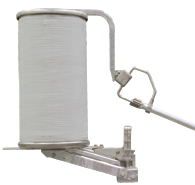
How does the pre-insertion inductor work?
First, an open-air arc makes up the initial circuit through the pre-insertion inductor. The inductor core picks up the inrush current before it reaches the main contact. Then, the pre-insertion inductor is bypassed, and disconnected as the moving arcing rod rotates. As the main contact is made, the pre-insertion inductor is completely removed from the circuit.

The sliding contact arrangement places the pre-insertion inductor in the circuit for only a few cycles. That’s how long it takes to provide high-quality transient control.
For complete application information on S&C Pre-insertion Inductors refer to S&C Data Bulletin 711-95 or contact the nearest S&C Sales Office.
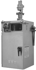
The Type CS-1A Switch Operator direct-drives the vertical-break disconnect of the Mark V Circuit-Switcher. It provides trip-free capability. Should the Mark V be inadvertently closed into a fault sensed by user-furnished relays, Mark V will trip immediately.
The operator features a sturdy welded enclosure with baffled louvers that allow air circulation, but keep out rain. The interior of the weatherproof, dustproof enclosure is accessed by a hinged door . . . rather than removal of the entire enclosure.
The Type CS-1A Switch Operator includes:
- Six adjustable auxiliary switch contacts, coupled to the motor
- External trip and close push buttons with padlockable cover
- Built-in manual operating handle for the disconnect
- Decoupling mechanism that allows decoupling and locking of the disconnect in the open position
- Mechanical position indicator
- Non-resettable operation counter.
Optional features for the Type CS-1A Switch Operator include:
- Additional auxiliary-switch contacts
- Position indicating lamps
- Remote-control blocking switch
- Space-heater thermostat
- Duplex receptacle with ground-fault circuit interrupter, and convenience light lampholder with switch.


